Product
Optipow105 Air Cleaning Valve V1617803-0200
Product Description
Construction: Diaphragm Plunger Pulse Jet Valve
Standard: Optipow Fabric Bag Collector
Operating Temperature : Low Temperature Resistant Design, -40°C-130°C
Application: industrial dust removal in thermal power plants, glass plants, cement plants, mining, industrial metallurgy, production workshops, etc
Advantage: 30 Years Experience Factory, Strict Quality Control System, Longer Service Life, Attractive Price, Original Accessories Available
Package: Special Foam Box
Production Capacity: 100000PCS/Month
Longer Service Life: More than Twice Service Life than that in the Same Industry
Interchange: Pulse Jet Valve, Optipow Fabric Filter
Assurance: One Year Free Quality Assurance Service
Service: 7*24 Hours Expert Consultation Online, Replacement Instead of Repair
Product Details
◆ Plunger Pulse Solenoid Valve Optipow 105
1. Introduction
The compact pulse valve for the Optipulse fabric filters of different types.
is a result of many years of experiences within the fabric filter technology area
is quick acting with high efficiency
has small dimensions, the figure after the name stands fir the diameter of the plunger
is primarily designed to be used in combination with circular pressure tank
is easy to install and make service to
has a very robust design, designed for normal use at air pressure up to 600kPa (6bar)
Normal max operating temperature (compact pulse valve) 50°C
2.Main Part

3.Dimesion sketch and assembly
For increasing the locking of all bolts, use LOCKTITE 577 or similar.

4. FUNCTION
Volume A connected to the pressure tank, via the slot between the valve house and the plunger. There is same pressure in the volume A as in the pressure tank. Due to the larger pressurised surface of the plunger in volume A, the plunger is pressed towards the pulse pipe and seals between the pressure tank and the pulse pipe. The volume B is via the solenoid valve connected to the pilot air. The area is larger on pilot air side so the pilot membrane is pressed down towards the top of the valve house and seals off the volume A from the ambient. | |
Opening When cleaning is initiated, the solenoid valve closes the connection (a) and opens to ambient (b) which means that volume B is evacuated. The membrane is pressed upward (c) and the volume A is evacuated through the 2 ports at the outer side of the valve house. The plunger is rapidly moving upwards by the pressure difference over the plunger. The compressed air in the pressure tank is released through the pulse pipe as a pulse and further on to a row of filter bags. | 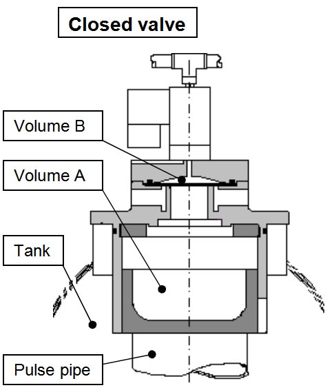 |
| Closing The solenoid is closed to ambient and opened to the pilot air. The pilot membrane is pressed down towards the seat. The pressure above the plunger will be equalised to the tank pressure via the slot between the plunger and the horse and the plunger moves down to the pulse pipe and ends the cleaning pulse. The time for a sequence (start opening to closed valve) is depending on process demands, i.e Volumeof pulse air per pulse and emission guarantees. | 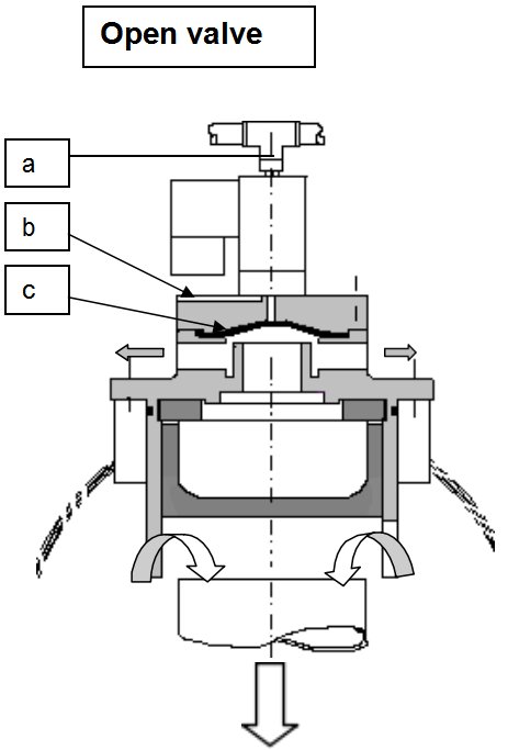 |
5. Installation
5.1 Assembly instruction
NOTE!
Before the assembly of the OPTIPOW units, an accurate cleaning of the internal of the pressure tank is of great importance. Any particle in the tank could in the future give serious problems regarding the operation of the pulse valves.
The OPTIPOW valve is as standard made for vertical installation. When the valve shall operate horizontally an extra internal spring has to be used. By that the plunger will always be in closed position when pressurising the cleaning system.
The OPTIPOW is normally delivered as one unit in a special package. For detailed instructions regarding erection of separate parts, see OPTIPOW assembly drawing.
Unpack the valves at first when mounting them.
Check that there are no visible damages on the valve.
Check that there are no foreign materials inside of the valve.
Check that the top of the pulse pipe is smooth without any burrs.
Position numbers below refers those mentioned in figure 1.
Put the plunger (pos 4) on the top of the pulse pipe. Lubricate the O-ring on the outer side of the valve house (pos 1) and match the house to the plunger. When installing the pulse valve be careful not to damage the O-ring. Tum the house so that the solenoid is pointing in right direction. Screw the four bolts with fingers as long as possible and make then the last setting with tool cross-wise to avoid damages to the O-ring. Torque according to specifications.
NOTE!
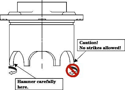
The valve house is sensitive to strikes on the bottom part of the house(see sketch below).
If the house is sutyected to a strike and the plunger is not able to move up and down inside the house, you may use a hammer or a conical tool to restore the shape of the taps of the housing, thus letting the plunger move freely up and down.
5.2 Notes regarding spare part installation
When receiving an OPTIPOW unit as spare part there are some additional points to consider at the installation.
Before dismounting the faulty OPTIPOW from the pressure tank, check the following.
• Unpack the valves at first when mounting them.
• Check that there are no visible damages on the valve.
• Check that there are no foreign materials inside of the valve.
• Check solenoid label, correct type mounted.
• ATTENTION! Make sure the pressure tank has been depressurised down to surrounding pressure.
NOTE!
Due to risk of particles, moist and other foreign objects, could enter the tank never leave the pressure tank unattended with an open tank hole. If job cannot be completed, remount the old OPTIPOW unit or in other way cover the hole. Never pressurizes an uncompleted tank.
Dismount the intended OPTIPOW unit.
Inject, through the hole, the condition of the internal of the pressure tank, particles, moist etc.
If necessary, clean the internal of the tank with a vacuum cleaner until satisfied result has been archived.
When mounting the spare part OPTIPOW, follow the assembly instruction given in section 5.1.
5.3 Pilot air connection
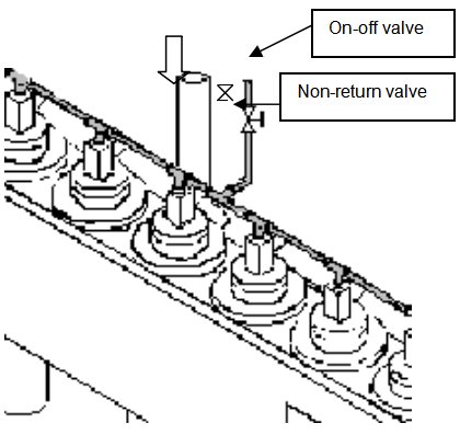
| The pilot air for the solenoid is taken from the incoming tube to the pressure tank. The pipefpr the pilot air is common for all valves in one tank and is connected upstream the main on- off valve of respective tank. The pipe should have an on-off valve and a non-return valve which ensures that pressure is kept also if pressure decreases during pulsing. |
Note: If a separate feeding pipe for the pilot air is used the pressure for the pilot air should be approx equal to pressure in tank. A too high pressure will give a remaining deformation to the membrane, which will reduce the lifetime and have a reducing effect on the function of the pulse cleaning. |
6.Testing of installation
General
When all pulse valves are mounted, the tank unit should be tested regarding leakage as well as function of the individual pulse valves. Principles for the testing and acceptable results should be according to description below.
Testing procedure for tank unit
1.Properly secure the complete assembly to the floor or a non-movable test fixture and then pressurize the tank unit to 200 kPa (2 bar) . Note that the pilot air should have the same pressure. Eliminate eventual leakage in the connections.
If it is impossible to achieve a pressure in the tank check the following points:
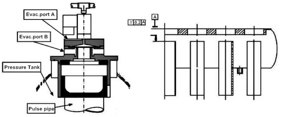
If there is a leakage through evacuation ports "B".
一 Check that the pilot air is connected and that there are no leakages in the connections.
一 Replace solenoid valve. Note the position of the mark on the side of the solenoid vs. The slit in the top cover when installing.
If a particular valve is leaking; dismount that and check that the plunge is operating free.
If necessary clean the surfaces.
If it is a common leakage; dismount all valves and check measure "A” , picture 8. If necessary, machine the surface of the pulse pipe. Note that the top of the pulse pipes must after machining be polished to avoid sharp edges and finally the tank has to be cleaned.
2.Turn off air supply.
3.Check pressure decrease in tank as a function of time. Allowed pressure decrease is 50 kPa per minute. Even if there is a higher leakage continue to 4.
4.Check the function of each valve by pulsing from 200 kPa. Repeat this for 3 cycles.
5.Repeat from 3. If the leakage still is high try to find out if there is some valve leaking more than other, dismount that and check plunge sealing surface and secondly measure "A" . If necessary, maching surface to right tolerance.
6.Mount valve and start from 3 again. This is to be repeated until an acceptable result is achieved.
7.The final result of the testing should be documented for each tank unit according to example on appendix A. A copy of the result should be returned back to the orderer but also enclosed with the pressure tank at delivery.
7. Error and detection diagram
General
In case of problems or failure occurs during testing please contacting our Helpdesk .
Error detection
Failure
Possible solution/Check
Valve does not pulse:
Has solenoid been turned during reassembly?
Pilot air connection done according to instructions, pressure level correct?
Particles in tank and/or valve (Air quality demands see Appendix B ) ?
Operating conditions Ok (temperature etc.) ?
Evacuation ports fully open (no scrap blocking air flow from pilot valve ) ?
Check On/Off valve turned on, non-retum valve correct positioned
Solenoid correct electric connection?
Leaking valve:
Tightness check done successfully (instructions) ?
All bolts assembled with correct torque?
O-ring sealing undamaged?
Membrane in good quality (no deformations and flexible ) ?
Check O-ring on solenoid.
◆ Plunger Pulse Solenoid Valve Optipow 105

| Product Name | Article Number | POS.No. |
| OPTIPOW 105(24VDC) | V1617803-0100 | ① |
| OPTIPOW 105 (110V 60Hz, 100V 50/60Hz) | V1617803-0200 | ① |
| OPTIPOW 105 (110V 50Hz) | V1617803-0300 | ① |
| OPTIPOW 105 (120V 60Hz) | V1617803-0400 | ① |
| OPTIPOW 105 (220V 50Hz) | V1617803-0500 | ① |
| OPTIPOW 105 (UR-CERTIFIED 120V 60Hz ) | V1617803-0600 | ① |
| OPTIPOW 105 (without solenoid, revolving 90° ) | V1617803-0800 | 一 |
| Coupling Set | V3592382-0000 | 一 |
| Membrane | V4549902-0100 | ② |
| O-Ring (Fluor rubber 64.5 x 3.1) | 8003-5573 | ③ |
| O-Ring (Nitril 70SH 64.5 x 3.1) | 2136-1422 | ③ |
| O-Ring (114.5 x 3.1) | 2136-1435 | ④ |
| Pilot Cover | V3630501-0100 | ⑤ |
| Plate | V3630524-0100 | ⑥ |
| Plunger | V3630527-0100 | ⑦ |
| Round Washer (SS3576-10-200HV FE/ZN45) | 4903-2173 | 一 |
| Rubber Disc | V3630530-0100 | ⑧ |
| Rubber Disc | V3640661-0100 | ⑧ |
| Solenoid Valve(24 V DC) | V3611471-0100 | ⑨ |
| Solenoid Valve (100 V, 60 Hz) | V3611471-0201 | ⑨ |
| Solenoid Valve (110 V, 50 Hz) | V3611471-0300 | ⑨ |
| Solenoid Valve (110 V, 60 Hz) | V3611471-0200 | ⑨ |
| Solenoid Valve (120 V, 60 Hz) | V3611471-0400 | ⑨ |
| Solenoid Valve (120V, 60 Hz-UL CERTIFIED) | V3640645-0200 | ⑨ |
| Solenoid Valve (230V, 50 Hz) | V3611471-0500 | ⑨ |
whatsapp:8618943497883 alex@starmachinechina.com


